
A produced water treatment package should be selected from a representative inlet-water profile and an agreed outlet destination. Capacity alone is not enough. Removing free oil and suspended solids does not establish that the water meets a discharge permit, reinjection specification or reuse requirement.
This guide explains the selection stage for modular oilfield water-treatment equipment: what to measure, how to define the process boundary and what to request from bidders. Final process design and environmental compliance require project-specific engineering and applicable local approvals.
Start with the outlet route
Identify whether treated water goes to an approved disposal facility, reinjection system, industrial reuse process or permitted discharge point. Obtain the destination’s acceptance criteria, sampling requirements and operating restrictions. These may involve more than oil-in-water concentration: suspended solids, salinity, scaling tendency, bacteria or other constituents can matter depending on the route.
Write down who approves the outlet specification and who is responsible for the permit or downstream facility. Avoid an RFQ that asks only for “environmentally compliant water.” A supplier cannot define a universal legal outlet limit for every field or country.
Use an inlet envelope, not one convenient sample
Provide normal, minimum and peak flow, water temperature and the expected variation over the project. Use a sampling plan that represents the wells and operating states the package will actually receive. Record collection conditions and laboratory methods; oil concentration results from different methods are not automatically interchangeable.
| Input | Selection consequence | Information to request |
|---|---|---|
| Free, dispersed and emulsified oil | Different separation behavior and pretreatment needs | Representative analysis and separation or treatability tests |
| Suspended solids and particle distribution | Wear, settling, filtration and sludge load | Expected solids range and residuals-handling arrangement |
| Dissolved salts and chemistry | Corrosion, scaling and possible additional treatment | Water chemistry matched to the intended outlet use |
| Production chemicals | Possible changes in emulsion stability and compatibility | Chemical identities, dosage range and supplier safety information |
| Flow and temperature changes | Buffer capacity, turndown and process stability | Operating envelope and response to out-of-range feed |
Match each process stage to a defined task
Buffering and bulk separation may address variable flow and separable oil. Depending on the water behavior, further stages may include chemical conditioning, flotation or filtration. Those are candidate functions, not a universal train: their suitability must be demonstrated for the intended feed and outlet target.
Conventional oil separation and particulate filtration do not remove dissolved salts merely because the outlet looks clear. Dissolved contaminants may require additional treatment, with its own energy, cleaning and concentrate-disposal implications. Ask the supplier to explain which contaminants each proposed stage addresses and which remain outside the package scope.
Where uncertainty remains, define laboratory or pilot work before committing to a final design. Specify the samples, operating conditions, analytical methods and decision criteria. An attractive process diagram is not evidence that a difficult emulsion will separate reliably.
Check the full modular installation boundary
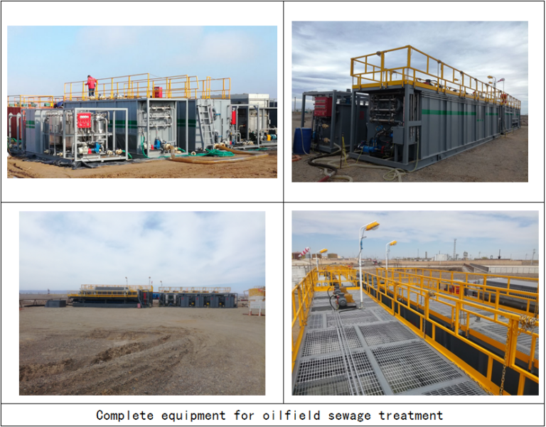
Request a layout showing feed and outlet connections, electrical supply, chemical storage, lifting points, access and drainage. Confirm shipping dimensions, transport condition and maximum module mass. Identify who provides foundations, interconnecting pipes, weather protection and site commissioning.
Make residuals explicit: separated oil, sludge, backwash and spent consumables need collection and an authorized handling route. Ask how operators isolate and clean equipment and what happens while one stage is unavailable. Relocation capability should include draining, preservation, transport and recommissioning, not only skid lifting points.
Link selection to verification
If upstream flow and water cut are still being established, data from the field’s well-testing program can help define the feed scenario, but it does not replace the treatment-specific laboratory analysis. Keep the water-analysis report, process assumptions and equipment proposal under the same revision control.
Once the process scope is selected, use the performance-guarantee checklist to agree inlet limits, outlet measurements, test duration and remedies. This separates selecting an appropriate process from proving the agreed result.
Send Vance Petroleum the water analysis and outlet requirements, together with flow cases, utilities, destination and mobility needs. Request a technical explanation of assumptions and exclusions before comparing the package price.
Continue your equipment research
Compare the equipment pages and technical notes most closely connected to this topic.