
Buyers comparing frac pumps for sale need more than a horsepower label and a maximum pressure figure. A field-ready frac pump is an integrated pressure-pumping unit: prime mover, transmission, triplex pump, fluid end, cooling system, manifolds, controls, chassis or trailer, safety functions, documentation and spare-parts scope. Two offers with similar headline ratings can deliver very different usable performance and ownership risk.
This guide provides a consistent method for comparing new, used and remanufactured units. It focuses on the operating envelope and complete delivered package so technical and commercial teams can evaluate offers on equal terms.
Define the duty before comparing frac pumps for sale
Start with the stimulation program. State the expected fluid system, proppant loading where relevant, normal and maximum treating pressure, required rate per unit, stage duration, duty cycle, number of units in the spread, ambient temperature, altitude and expected annual utilization. A supplier can then discuss a suitable oilfield fracturing truck and pump package rather than selecting hardware from one maximum value.
Pressure and flow must be expressed together. Ask each supplier to identify the proposed simultaneous operating points and any time or temperature limitations. A maximum pressure reached only at a low rate is not equivalent to the rate required by the treatment schedule. The same applies to power: advertised engine output is not the same as power available at the pump after transmission, accessory and environmental losses.
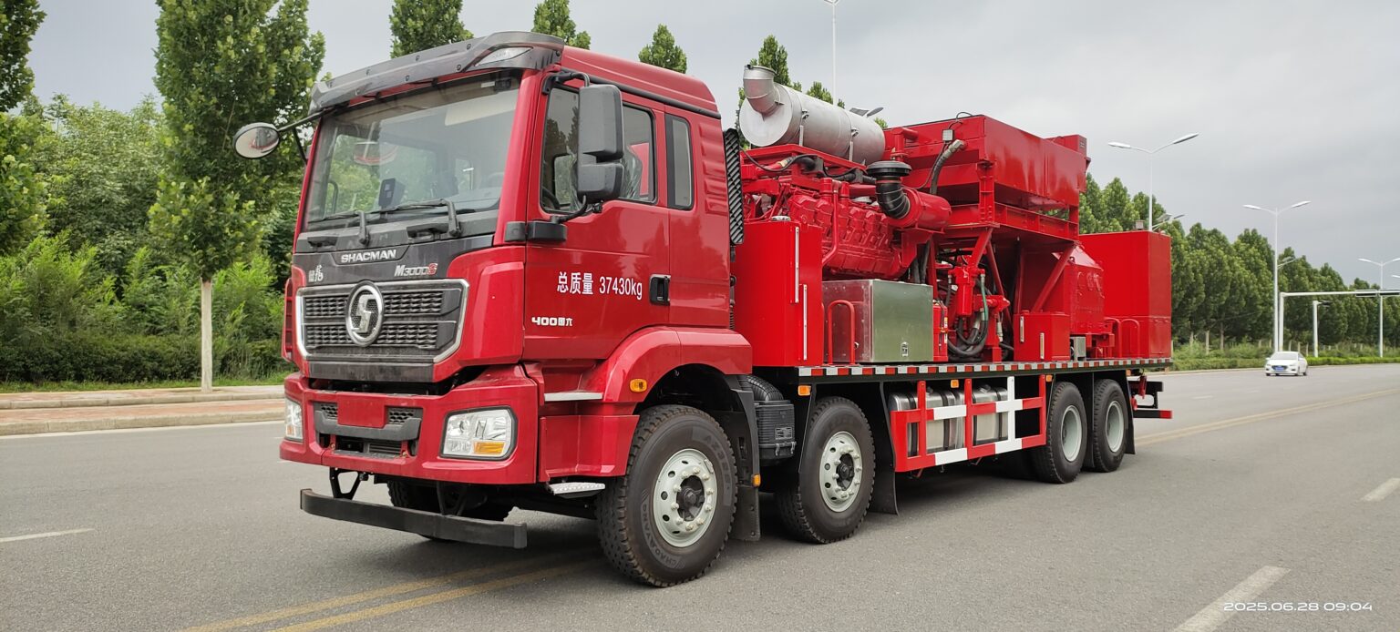
Compare the pressure-rate-power envelope
Request a table or curve showing pump speed, discharge pressure, rate and required input power at the operating points important to the project. Clarify plunger size, fluid-end configuration, allowable speed range and the assumptions used for mechanical and volumetric efficiency. If multiple plunger sizes are offered, determine which changeovers are realistic for the field crew and what parts are included.
The triplex plunger pump cannot be evaluated separately from the prime mover and transmission. Engine torque, gear ratios, driveline limits, torsional behavior and control logic affect how the unit accelerates, holds a set point and responds to changing pressure. Cooling capacity must cover the engine, transmission, lubrication and other heat loads under the stated ambient conditions.
| Comparison area | Buyer input | Supplier evidence |
|---|---|---|
| Operating envelope | Normal and maximum pressure, rate and duration | Simultaneous operating points, pump speed and power requirement |
| Power train | Duty cycle, altitude, climate and fuel constraints | Engine, transmission, ratios, derating basis and cooling arrangement |
| Fluid end | Fluid chemistry, proppant and maintenance strategy | Material, plunger size, pressure rating, service limits and consumables |
| Integration | Road limits, fleet layout and operator requirements | Weight distribution, manifolds, controls, access and safety functions |
| Acceptance | Inspection, witness and record requirements | Inspection plan, function checks, pressure-test boundary and reports |
Review the systems that determine reliability
Fluid end and consumable parts
Review the fluid-end material, valve and seat arrangement, packing, plungers, discharge connections and access for routine work. Ask for recommended inspection intervals based on the proposed duty, while recognizing that actual life depends on fluid, proppant, pressure cycle, operating practice and maintenance. A useful offer identifies the initial consumables and the recommended stock for the buyer’s expected utilization.
Transmission, lubrication and cooling
Transmission selection must match engine torque and pump demand through the usable speed range. Confirm lubrication capacity, filtration, monitoring and service points. The related oilfield transmission package should be evaluated with the driveline and pump rather than as an isolated gearbox. Ask how temperatures are monitored and what alarm or shutdown functions protect the equipment.
Manifolds, controls and operator access
Confirm the pressure-containing boundary from the pump outlet through the unit manifold, including valves, fittings, relief arrangements and connections to the spread. Review the control station for visibility of pressure, rate, speed, temperature and alarm status. Service access should allow safe inspection and replacement of routine wear components without unnecessary removal of unrelated equipment.
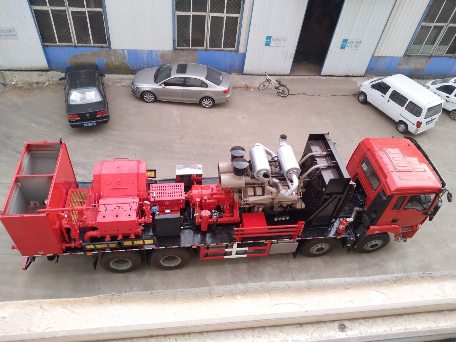
New, used and remanufactured units require different evidence
For a new unit, compare the proposed component list, data sheet, drawings, inspection plan, documentation schedule and warranty boundary. Configuration remains project-specific; a catalog model should not replace a signed technical specification.
For a used frac pump, request serial information, operating hours where credible, maintenance history, event or alarm records where available, fluid-end condition, power-train condition, control-system support and evidence of previous repairs. Verify whether replacement parts and software support remain available. A visual inspection alone cannot establish the condition of pressure-containing and internal rotating components.
For a remanufactured unit, require an itemized scope. Identify which assemblies were disassembled, measured, repaired, replaced and tested. Record the acceptance limits and the remaining used components. “Remanufactured” should describe documented work, not paint and selected external parts.
Normalize the delivered commercial scope
Price comparisons should use the same boundary. Separate the base pump unit from project engineering, testing, documentation, spare parts, training, packing, freight and commissioning. Clarify whether high-pressure iron, hoses, data interfaces, special tools and initial consumables are included or excluded.
- Base equipment: chassis or trailer, engine, transmission, pump, cooling, manifolds and controls.
- Verification: agreed function tests, pressure tests, witnessed points and issued records.
- Operating readiness: commissioning, training, consumables, tools and recommended spares.
- Documentation: drawings, data sheets, manuals, parts lists and destination documents.
- Logistics: packing, inland transport, freight, insurance and receiving responsibilities.
Use the existing fracking pump truck fleet checklist to compare fleet count, redundancy and service strategy after the individual unit scope is clear.
RFQ checklist for a frac pump package
- Provide the treatment pressure-rate schedule and stage duration.
- Describe fluid, proppant, expected duty cycle and annual utilization.
- State altitude, ambient range, fuel and destination requirements.
- Define chassis or trailer limits and fleet-layout constraints.
- List control, data, alarm and shutdown expectations.
- Specify the pressure-containing boundary and connection interfaces.
- Request simultaneous operating points and the power basis behind them.
- Define inspection, testing, documentation and witness requirements.
- State training, commissioning, spares and special-tool needs.
- Confirm the delivery schedule and commercial delivery boundary.
Vance Petroleum can review these inputs for a project-specific pressure-pumping configuration. Send the treatment envelope, duty cycle, destination and requested documentation through the technical inquiry form to receive a focused technical and commercial discussion.
Continue your equipment research
Compare the equipment pages and technical notes most closely connected to this topic.